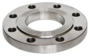

Slip On Flange
Slip ON
Slip On Flange, listed in sizes 1/2" to 48", with design references ANSI 16.5, EN 1092-1. Applications listed by GMC: Connect valves with pipe, pipe fittings.
- Type / operation
- Slip On
- Sizes
- 1/2" – 48"
Manufactured by General Manufacturing Concern (Pvt.) Ltd., whose quality management system is certified to ISO 9001:2015. This is a company certification, not a certification of this individual product. Certificate details
32 values on this page are being confirmed with GMC. These are highlighted in the dimension tables and explained underneath. Please confirm them before using them for design.
Standards & applications
Design & compliances
- ANSI 16.5
- EN 1092-1
Applications listed by GMC
Connect valves with pipe, pipe fittings.
Dimension key
- A
- PCD Pinch Circle
- D
- Outer Dia
- C
- Raised Face Dia
- B
- Thickness
- RF
- Raised Face Thickness
- F
- Bolt Dia
- N
- No. of Holes
Dimensions
DIMENSIONS (INCH) - RAISED FACE - CLASS 150
| Size | 1/2" | 3/4" | 1" | 1.25" | 1.5" | 2" | 2.5" | 3" | 4" | 5" | 6" | 8" | 10" | 12" | 14" | 16" |
|---|---|---|---|---|---|---|---|---|---|---|---|---|---|---|---|---|
| A | 60.3 | 69.8 | 79.4 | 88.9 | 98.4 | 120.6 | 139.7 | 152.4 | 190.5 | 215.9 | 241.3 | 298.4 | 361.9 | 431.8 | 476.2 | 539.7 |
| D | 88.9 | 98.4 | 107.9 | 117.5 | 127 | 152.4 | 177.8 | 190.5 | 228.5 | 254 | 279.4 | 342.9 | 406.4 | 482.6 | 533.4 | 596.9 |
| C | 34.9 | 42.9 | 50.8 | 63.5 | 73 | 92.1 | 104.8 | 127 | 157.2 | 185.7 | 215.9 | 269.9 | 323.8 | 381 | 412.7 | 469.9 |
| B | 11.1 | 12.7 | 14.3 | 15.9 | 17.5 | 19 | 22.2 | 23.8 | 23.8 | 23.8 | 25.4 | 28.6 | 30.2 | 31.7 | 34.9 | 36.5 |
| RF | 1.6 | 1.6 | 1.6 | 1.6 | 1.6 | 1.6 | 1.6 | 1.6 | 1.6 | 1.6 | 1.6 | 1.6 | 1.6 | 1.6 | 1.6 | 1.6 |
| F | 4 | 4 | 4 | 4 | 4 | 4 | 4 | 4 | 8 | 8 | 8 | 8 | 12 | 12 | 12 | 16 |
| N | 15.91 | 15.92 | 15.93 | 15.94 | 15.95 | 196 | 197 | 198 | 199 | 22.210 | 22.211 | 22.212 | 25.413 | 25.414 | 28.615 | 28.616 |
DIMENSIONS (INCH) - RAISED FACE - CLASS 150
| Size | 18" | 20" | 22" | 24" | 26" | 28" | 30" | 32" | 34" | 36" | 38" | 40" | 42" | 44" | 46" | 48" |
|---|---|---|---|---|---|---|---|---|---|---|---|---|---|---|---|---|
| A | 577.8 | 635 | 692.1 | 749.3 | 806 | 864 | 914 | 978 | 1029 | 1086 | 1149 | 1200 | 1257 | – | – | – |
| D | 635 | 698.5 | 749.3 | 812.8 | 870 | 927.1 | 984.3 | 1060.5 | 1111.3 | 1168.4 | 1238.3 | 1289 | 1346.2 | – | – | – |
| C | 533.4 | 584.2 | 641.2 | 692.1 | 749.3 | 800.1 | 857.3 | 914.4 | 965.2 | 1022.4 | 1073.2 | 1124 | 1193.8 | – | – | – |
| B | 39.7 | 42.9 | 46 | 47.6 | 68.3 | 71.4 | 74.7 | 81 | 82.6 | 90.4 | 90.4 | 90.4 | 96.8 | – | – | – |
| RF | 1.6 | 1.6 | 1.6 | 1.6 | 1.6 | 1.6 | 1.6 | 1.6 | 1.6 | 1.6 | 1.6 | 1.6 | 1.6 | – | – | – |
| F | 16 | 20 | 20 | 20 | 24 | 24 | 28 | 28 | 28 | 32 | 32 | 36 | 36 | – | – | – |
| N | 31.717 | 31.718 | 34.919 | 34.920 | 35.121 | 35.122 | 35.123 | 41.124 | 41.125 | 41.126 | 41.127 | 41.128 | 41.129 | 41.130 | 41.131 | 41.132 |
Dimensions in the units shown, as published on the GMC datasheet. Dimensions are nominal and subject to the manufacturer's standard tolerances. "–" means no value is given for that size. Scroll sideways to see all sizes.
- 1. N at 1/2": Row N (No. of Holes) appears to contain bolt diameters; rows F and N may be swapped on the datasheet. Back to table
- 2. N at 3/4": Row N (No. of Holes) appears to contain bolt diameters; rows F and N may be swapped on the datasheet. Back to table
- 3. N at 1": Row N (No. of Holes) appears to contain bolt diameters; rows F and N may be swapped on the datasheet. Back to table
- 4. N at 1.25": Row N (No. of Holes) appears to contain bolt diameters; rows F and N may be swapped on the datasheet. Back to table
- 5. N at 1.5": Row N (No. of Holes) appears to contain bolt diameters; rows F and N may be swapped on the datasheet. Back to table
- 6. N at 2": Row N (No. of Holes) appears to contain bolt diameters; rows F and N may be swapped on the datasheet. Back to table
- 7. N at 2.5": Row N (No. of Holes) appears to contain bolt diameters; rows F and N may be swapped on the datasheet. Back to table
- 8. N at 3": Row N (No. of Holes) appears to contain bolt diameters; rows F and N may be swapped on the datasheet. Back to table
- 9. N at 4": Row N (No. of Holes) appears to contain bolt diameters; rows F and N may be swapped on the datasheet. Back to table
- 10. N at 5": Row N (No. of Holes) appears to contain bolt diameters; rows F and N may be swapped on the datasheet. Back to table
- 11. N at 6": Row N (No. of Holes) appears to contain bolt diameters; rows F and N may be swapped on the datasheet. Back to table
- 12. N at 8": Row N (No. of Holes) appears to contain bolt diameters; rows F and N may be swapped on the datasheet. Back to table
- 13. N at 10": Row N (No. of Holes) appears to contain bolt diameters; rows F and N may be swapped on the datasheet. Back to table
- 14. N at 12": Row N (No. of Holes) appears to contain bolt diameters; rows F and N may be swapped on the datasheet. Back to table
- 15. N at 14": Row N (No. of Holes) appears to contain bolt diameters; rows F and N may be swapped on the datasheet. Back to table
- 16. N at 16": Row N (No. of Holes) appears to contain bolt diameters; rows F and N may be swapped on the datasheet. Back to table
- 17. N at 18": Row N (No. of Holes) appears to contain bolt diameters; rows F and N may be swapped on the datasheet. Back to table
- 18. N at 20": Row N (No. of Holes) appears to contain bolt diameters; rows F and N may be swapped on the datasheet. Back to table
- 19. N at 22": Row N (No. of Holes) appears to contain bolt diameters; rows F and N may be swapped on the datasheet. Back to table
- 20. N at 24": Row N (No. of Holes) appears to contain bolt diameters; rows F and N may be swapped on the datasheet. Back to table
- 21. N at 26": Row N (No. of Holes) appears to contain bolt diameters; rows F and N may be swapped on the datasheet. Back to table
- 22. N at 28": Row N (No. of Holes) appears to contain bolt diameters; rows F and N may be swapped on the datasheet. Back to table
- 23. N at 30": Row N (No. of Holes) appears to contain bolt diameters; rows F and N may be swapped on the datasheet. Back to table
- 24. N at 32": Row N (No. of Holes) appears to contain bolt diameters; rows F and N may be swapped on the datasheet. Back to table
- 25. N at 34": Row N (No. of Holes) appears to contain bolt diameters; rows F and N may be swapped on the datasheet. Back to table
- 26. N at 36": Row N (No. of Holes) appears to contain bolt diameters; rows F and N may be swapped on the datasheet. Back to table
- 27. N at 38": Row N (No. of Holes) appears to contain bolt diameters; rows F and N may be swapped on the datasheet. Back to table
- 28. N at 40": Row N (No. of Holes) appears to contain bolt diameters; rows F and N may be swapped on the datasheet. Back to table
- 29. N at 42": Row N (No. of Holes) appears to contain bolt diameters; rows F and N may be swapped on the datasheet. Back to table
- 30. N at 44": Row N (No. of Holes) appears to contain bolt diameters; rows F and N may be swapped on the datasheet. Back to table
- 31. N at 46": Row N (No. of Holes) appears to contain bolt diameters; rows F and N may be swapped on the datasheet. Back to table
- 32. N at 48": Row N (No. of Holes) appears to contain bolt diameters; rows F and N may be swapped on the datasheet. Back to table
Price the slip on flange for your project
This product is added to the form for you. Add the sizes, quantities and any material or testing requirements.